Creating a 3D System
CS 357 HW2
due Monday, March 16
(though I may give out HW3 before then)
In this assignment you will create a 3D viewing system from scratch, using only the 2D features of OpenGL. It would be fairly simple to modify this program to run in any windowing system that has basic line-drawing capabilities.
When your program opens up it should look like this, though your control panel probably won't be attached:
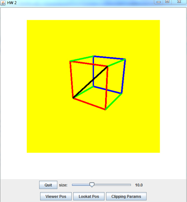
The drawing window should show a rectangular viewport shaded in a color different from the window's background, so it is easily seen. Within this viewport there is a line drawing of a cube. This cube should have one vertex at the origin, and sides extending along the standard axes. An adjustable SIZE parameter controls the size of the cube. 3D line drawings can be difficult to see as 3D objects. I find that it helps me to keep my bearings if I draw the diagonal of one of the faces of the cube. In the image above you can see the diagonal of the red face of the cube drawn in black. The point of the yellow viewport is that if you move the viewer closer to the cube, or decrease theta, or increase SIZE, you should be able to see the cube being clipped to the viewport.
In addition to the SIZE, you have a number of controls. One set allows a change in the x, y, or z coordinates of the viewer's position. Another allows changes in the x, y, z coordinates of the point the viewer is looking at. If you set the viewer to look at one of the vertices of the cube and then move the viewer around, the cube will appear to rotate around this vertex. A third set of controls allows you to adjust the clipping parameters: distance from the viewer of the Hither plane, the Yon plane, and the picture plane. Finally, there is a control for Theta, the view angle.
There is a lot to do to set this up. I suggest that you break it up as follows. Of course, if another plan makes more sense for the way you work, go with it; the important thing is to get this done and to allow time for bug fixes. Here is how I would go at it:
-
The interface is easy to build, so do that first. Assign variables with reasonable defaults to each of the controls. The callbacks should all be easy. For example, I have a slider called viewerXSlider that changes a variable I call viewerX. If you give variables like viewerX, viewerY, lookatX, lookatY, and so forth reasonable initial values it will help you in step 3. You might use the example on the back of the View Transformations handout for initial values. There is a lot of code here but it should all be easy code.
-
Make a viewport within your drawing area and color it in.
-
Now for the lengthy part. You need to implement the entire view tranformation as a product of matrices. When the viewer's location or the lookat point, the matrices needed to compute V change. Similarly, changing Theta changes the window boundaries and W, but doesn't require you to recompute V or P. You will have to implement matrix multiplication, which should not be a big problem, in order to compute the matrix pipeline.
-
Implement a line drawing method. This should input world coordinates for the endpoints of the line, and use the view transformation you implemented in step 3 to convert world coordinates to screen coordinates, then call openGL routines to actually draw the lines in your viewport.
-
Check out everything so far. It should be easy to tell if it is working correctly -- just have the viewer look at a vertex, and move the viewer around. It should appear as though the cube is moving around this fixed vertex.
-
Add clipping, to cut off any line at the edges of your viewport, and also at the Hither and Yon planes. If you move the Hither plane slowly away from the viewer towards the cube you should see the edges of the cube gradually cut off. There are a lot of details to keep straight here. This is the most difficult step of the entire project.
-
Add the Theta callback, and anything else that is missing. By the time you hand in the program all of the controls should be working correctly.
Spend some time working with your program after it seems to be complete. There are lots of interactions between the various controls; make sure that everything works correctly in all situations. In particular, ask yourself if the right thing happens when you change theta, and when you change the perspective constants H, D, and Y.
Implementation Notes: You are free to do this any way you want (except by using OpenGL's 3D primitives), but here are some things that I found useful.
-
I made wrapper classes for Points, Vectors, Lines, and Matrices. The code for each of these is easy and they help to organize your program. To avoid passing a data all through the program, I didn't do any of the graphical work in the wrapper classes. The Vector class has a method for transforming a vector by a matrix, but it doesn't know about the pipeline matrices V, P, and W.
-
If you want to know the most difficult bug for me to find, it was in converting between classes. My Matrix class has a general method for mutiplying two matrices, producing a matrix. To transform a vector by a matrix I had to convert the vector to a matrix,do the multiplication, then convert the resulting matrix back to a vector. In this final conversion I used the Vector contructor, which automatically set the 4th coordinate to 1. So for the pipeline I start with a Point, convert it to a Vector, convert that to a 1x4 Matrix, multiply by V, multiply by P, multiply by W, then convert the result back to a Vector and normalize it by dividing by its 4th coordinate. You see the problem -- I was setting the 4th coordinate to 1 before normalization. This was easy to fix once I found it, but not so easy to find.
-
The environment here is pretty complicated; it is hard to debug the program by just debugging the individual functions. To help with this, I added a button called "Print Stuff" to my interface. The callback function I modified as needed to print whatever I wanted to know when the button was clicked. At one stage I had it print the current versions of V, P, and W. At another stage I started with a specific point p and had it print out the individual results of transforming by V, by P, by W, and normalizing. That was how I found the normalization bug.
-
I'll leave it up to you to design whatever user interface you want. You will need 11 sliders for changing the various values for the viewer, lookat, and clipping parameters. You don't have to do it this way, but I found it easy to make popup frames to hold groups of these sliders. You can make a frame for each group and add the controls to it; just don't set the visibility parameter of the frame to true. Give a button on the main control panel whose callback sets the frame's visibility to true.
-
I would like your program to provide some kind of feedback on where each slider it set to. The sliders in the Swing framework have an optional parameter that prints a scale underneath the slider; I've found that awkward to use. In my program I put a label just to the right of each slider; the callback function for the slider uses this label's setText( ) method to display the slider's current value. Beware that when you call the slider's setValue( ) method to set up its initial value, the callback method is invoked. If the callback method call's the label's setText( ) method, the label has to exist before you set the slider's value.
-
When I was first setting up my version of the program I had each of my callbacks call the drawBox( ) function that draws the cube. This was wrong. The callbacks just change the pipeline matrices. The drawBox( ) method should be called from your display( ) method (which itself is called repeatedly by the system which is trying to maintain a desired frame rate) and it will draw the cube using whatever the current values are for the pipeline matrices.
Extra Credit Option: If you finish this early and are looking for something extra to do, try to make your cube a solid with polygonal sides rather than lines for edges. The difficulty here is clipping a polygon rather than a line. Draw some pictures and work out an algorithm for clipping a rectangle to the viewport. Since you are only displaying a cube here, you only need to clip rectangles, not arbitrary polygons, to the viewport. The Watt text discusses polygon clipping in section 6.1 The text by Foley and van Dam (which I used to use in this course until it got too far out of date) also has a good discussion of polygon clipping in general. You can find either of these in the library or borrow them from me. I'll give up to 10 bonus points, plus Honor and Glory, to anyone who implements polygon clipping.