You have the option to use either DLSim or Minecraft to build the logical circuits in this assignment. If you use Minecraft, instead of using handin, you must send me a youtube video demoing your circuit and explaining how it works.
In this assignment, you will use DLSim to simulate digital logic circuits.
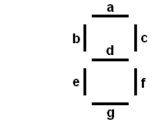
1. Design a combinational logic circuit which will drive a 7-segment LED display:
The input to circuit is a set of 4 signals a3, a2,
a1, a0 representing the digits of a 4-bit
binary number. The output is a set of the seven signals a,
b, c, d, e, f, and g used to drive the seven segments of the LED
display. Each of the outputs can be represented as a boolean
function of the four input variables. For example, if the
input is the number 5 (i.e., 0101 in binary), then segments a, b,
d, f, and g should be on (1), while c and e are off (0). For
input values greater than 9, you may either display an 'E' to
indicate an error, or treat it as a "don't care" condition.
Save your circuit as an xml project in a file called leddriver.xml.
2. Design a 16-bit adder/subtractor. The input to the
circuit consists of:
a. two 16-bit integer values
b. a mode bit labeled add/sub, indicating whether to add or subtract
(add when the signal is 0, subtract when it is 1)
c. a carry/borrow in bit. When it is 1 on add, it
means there is a carry in; when it is 1 on subtract, it means
there is a borrow in.
The outputs are:
a. a 16-bit integer sum/difference
b. a carry/borrow out bit (The borrow out bit should
be set if there is no carry out of the most significant bit when a
subtraction is performed.)
The operation of the circuit is shown in the following table:
| mode |
Cin | operation |
how to compute |
| 0 |
0 |
a + b |
a + b |
| 0 |
1 |
a + b + 1 |
a + b + 1 |
| 1 |
0 |
a - b |
a + b + 1 |
| 1 |
1 |
a - b - 1 |
a + b |
I am providing a 4-bit adder chip to help you get started.
I suggest developing your adder/subtractor in the following steps:
a. Extend the 4-bit adder to a 16-bit adder.
b. Design the 16-bit adder/subtractor using a 16-bit adder
and a 16-bit xor.
Save your circuit as an xml project called addsub16.xml.
a. Choose an alphabet for your output.
b. Design a logic circuit which will drive the 7-segment
LED display, making it possible to display each of the characters
in your alphabet. The number of inputs of the circuit will
depend on the number of characters in your alphabet. For
example, if you want to be able to display 12 characters, then the
input should be 4 lines which can represent the bits of a binary
number in the range 0-11. In my example, I had 7 characters
(including a space), so I needed a minimum of log2(7)
(rounded up to the nearest integer) input lines.
You need to assign a binary code to each of the characters in
your alphabet. For example, I used the number 2 (i.e., 010
in binary) to represent 'E'. When the three inputs to my
circuit take on the values 0, 1, and 0, I want the a, b, d, e, and
g segments on, while segments c and f are off.
Make a truth table showing the relationship between the inputs
and the outputs. Each of the 7 segments is a boolean
function of the inputs. The
function of the LED driver circuit is to compute these seven
functions.
Your completed circuit should contain one LED driver component
for each LED you use.
d. Some additional logic is needed to determine which
alphabet characters are displayed on each LED for each value of
the counter. You can use combinational logic for this.
The outputs from the circuit are used as inputs to your LED
driver. The inputs to the circuit are the output lines from
the counter. So
number of outputs = (number of LEDs) x (number of inputs to the
LED driver)
number of inputs = number of bits in the counter
Each of the outputs is a boolean function of the inputs.
Again, you can design circuits to compute these functions by first
writing a truth table for each one.
Use at least 4 LEDs, at least 8 characters in your alphabet, and
at least 5 states for your sign.
Save your circuit as an xml project.