Connectors
Circuit Design
... Connectors
A connector models a carrier for a single or parallel-bus connection
with multiple input and output terminals. It is generally used to
distribute a single (or bus) output value to multiple inputs, but it
also permits multiple outputs to be "fed" to multiple inputs.
Adding a Connector to the Circuit Board
Adding a connector is different from adding other components, since the
connection terminals are specified sequentially. To add a connector, do
the following: - Select TB

- Left-click on the circuit board; this will specify the first
connection terminal.

- Continue left-clicking on the circuit board to specifiy
additional connection terminals.

- Double-left-click on the circuit board to specify the final
connection terminal.

Moving a Connector
- Click and drag a connection terminal to move that terminal only.
- Click and drag a line segment to move its endpoints.
- Select the entire connector and drag any line segment to move
the entire connector.
Adding and Deleting Connection Terminals
- To add a connection terminal right-click the connector at the
desired location and select Add Terminal.
- To delete a connection terminal right-click the terminal and
select Delete Terminal.
Multiplicity
Right-click anywhere on the connector and select Set Multiplicity.
Using Connectors
Connectors obey the following rules: - Any single input is distributed to all outputs;
- The disjunction of multiple inputs is distributed to all
outputs;
- Connectors connected in series act like a single connector; Note: the system will reject loops in connector sequences.
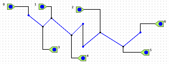
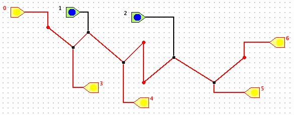
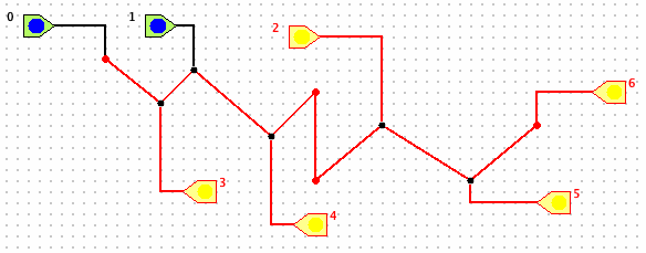
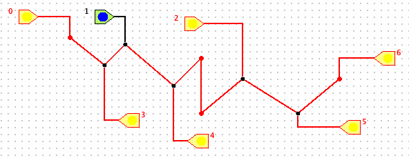
The following figures show two connectors in series and illustrate
connector behavior. 


