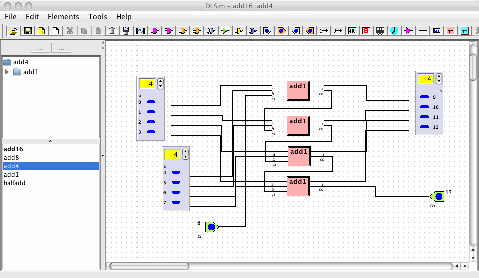
The following example shows the add4 subcircuit with bank pins selected for its 4-bit a and b input terms and its 4-bit s sum output.

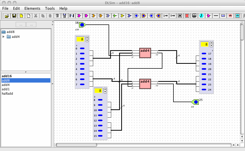
Here we see the add4 used in add8. Note the use of both bus pins (for a, b and s) and single-bit pins (for cin and cout).

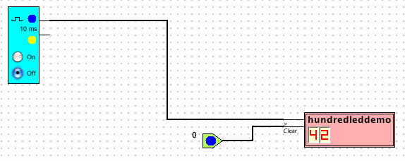
 ) used in a circuit are made visible when the
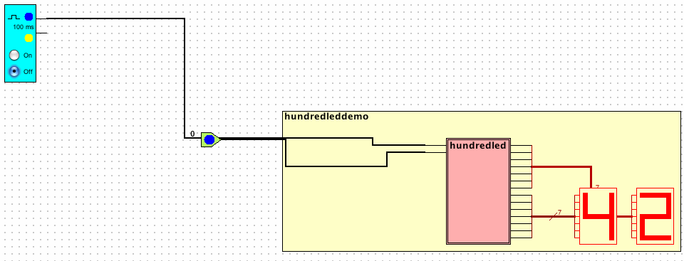
circuit is used as a subcircuit. This is shown in the example below.


The LED sequence in the subcircuit is by default based on the order in which the LEDs were added to the original circuit. This sequence can be specified by the user through the LED's Set LED Order action, using 0 for the left-most LED, 1 for the next, etc.