There are 2 constructors used in UserPluginView extensions. You must include both of the following constructors in your class:
public class MyPluginView extends UserPluginView {

   public MyPluginView(DLPlugIn plugin) {
     super(plugin);
   }

   public MyPluginView() {
     super()
   }
}
No other initialization steps are required in the constructors.
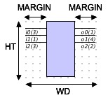
The standard footprint of a user-defined view will follow the same pattern as the default view: a rectangular box with input and output pins distributed respectively on the left and right. However, the extension is fully responsible for determining its size (by setting the WD and HT properties) and may determine its pin length by setting the MARGIN property. The WD and HT properties must be set in the setup method. The default MARGIN is 30. The following diagram shows these properties.
Note that when a standard footprint is used, the actual value of HT will always be large enough to accomodate the pin set, regardless of the value set during construction.
The component footprint is defined using java.awt.Graphics.drawPolygon(int[] xPoints, int[] yPoints, int nPoints) and java.awt.Graphics.fillPolygon(int[] xPoints, int[] yPoints, int nPoints). The xPoints, yPoints and nPoints parameters are derived from the property int[][] polygon
The first part of defining a non-standard footprint is to set this property. For example, here is a simple diamond-shaped footprint (shown without pins), with vertex coordinates as shown:
Traversing the polygon from the top in the counterclockwise direction, this footprint would be specified with the following code: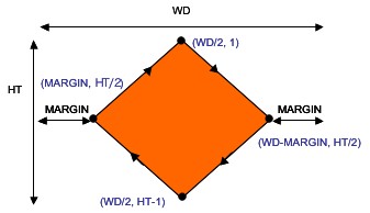
int MARGIN = getMARGIN();
int[][] poly = new int[][]{WD/2, WD-MARGIN, WD/2, MARGIN},
                          {1, HT/2, HT-1, HT/2}
setPolygon(poly);
As a second example, consider the ALU displayed below (without pins),
also showing the coordinates of the vertices. Tracing the polygonal path clockwise from the top, this ALU would be created using the following code: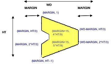
int MARGIN = getMARGIN();
int z1 = MARGIN, z2 = WD-MARGIN, z3 = MARGIN +15;
int[][] poly
  = new int[][]{{z1, z2, z2, z1, z1, z3, z3, z1},
 		{1, HT/3, 2*HT/3, HT-1, 2*HT/3, 5*HT/9, 4*HT/9, HT/3}};
setPolygon(poly);
When using a nonstandard footprint you may also need to define nonstandard pin placement. Nonstandard pin positioning is described using 4 arrays containing PinDesc objects. The PinDesc class is defined as follows:
public static class PinDesc {
   public int posNo, start, len;
   public PinDesc(int posNo, int start, int end){
	this.posNo = posNo;
	this.start = start;
	this.len = end;
   }
}
Each PinDesc object describes one physical pin. The parameters
have the following significance. There is one array containing pin descriptions for each of the 4 sides of the component: topPins, botPins, leftPins, and rightPins.
- posNo
- Pos number determined by inMap/outMap.
- start
- Pixel position from left or top (depending on whether the pin is, respectively, horizontal or vertical).
- len
- Pin length. Pins are drawn from the edge of the component inward.
Consider again the diamond plug-in, to which we have added one horizontal (pin 0) and one vertical (pin 1) pin.
The following code establishes this pin configuration:
int WD = getWD();
int HT = getHT();
int MARGIN = getMARGIN();
int z = WD/2-MARGIN;
PinDesc[] topPins = new PinDesc[]{new PinDesc(0, MARGIN+z/2, HT/3)};
PinDesc[] rightPing = new PinDesc[]{new PinDesc(1, 2*HT/3, MARGIN+z/2)};
setTopPins(topPins);
setRightPins(rightPins);
As a second example consider again the ALU from the previous
example. An 8-bit wide ALU (BITWIDTH = 8), its pin configuration is
declared as follows:
public ALU8() {
   setInputSize(19);
   setOutputSize(9);
   setInMap(BITWIDTH, BITWIDTH, 1, 1, 1);
   setOutMap(BITWIDTH, 1);
   setLabels("A0-A7", "B0-B7", "Cin", "f1", "f0", "C0-C8", "Cout");
}
The following diagram illustrates how the parameters for PinDesc are obtained. The code that establishes this pin configuration is shown below: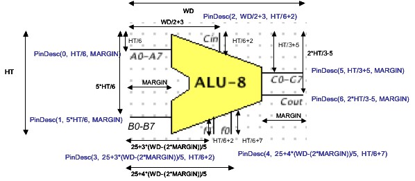
int WD = getWD();
int HT = getHT();
int MARGIN = getMARGIN();
PinDesc[] topPins = new PinDesc[]{new PinDesc(2, WD/2+3, HT/6+2)};
PinDesc[] leftPins =
     new PinDesc[]{new PinDesc(0, HT/6, MARGIN),
		   new PinDesc(1, 5*HT/6, MARGIN)};
PinDesc[] botPins =
     new PinDesc[]{new PinDesc(3, 25+3*(WD-(2*MARGIN))/5, HT/6+2),
	           new PinDesc(4, 25+4*(WD-(2*MARGIN))/5, HT/6+7)};
PinDesc[] rightPins =
     new PinDesc[]{new PinDesc(5, HT/3+5, MARGIN),
		   new PinDesc(6, 2*HT/3-5, MARGIN)};
setTopPins(topPins);
setLeftPins(leftPins);
setBotPins(botPins);
setRightPins(rightPins);
| WD | Component width (required). | |
| HT | Component height (required). | |
| MARGIN | Pin length, in the standard footprint (default: 30). | |
| BGCOL | Background color (default: Color(200, 200, 255). | |
| noName | If true, name is not printed (default: true). | |
| nameX | x-coordinate of name (required, if printed) (. | |
| nameY | y-coordinate of name (required, if printed). | |
| polygon | Polygonal footprint (required for nonstandard footprint). | |
| polySize | Number of vertices in polygonal footprint (required for nonstandard footprint). | |
| botPins | Bottom pin description list (for nonstandard pin positioning). | |
| topPins | Top pin description list (for nonstandard pin positioning). | |
| leftPins | Left pin description list (for nonstandard pin positioning). | |
| rightPins | Right pin description list (for nonstandard pin positioning). |
Swing controls may be added to the face of the plug-in by overriding the method public void panelSetup(). The default implementation of this method sets up the LED array. Inasmuch as your view class extends UserPluginView, which is itself an extension of javax.swing.JPanel, use panelSetup() to add components as you would for any GUI application. Bear in mind, however that the rectangle covered by the JPanel includes the pin area. If you use a layout manager, you may find it useful to insert left and right insets of width MARGIN.
Here is an example that installs a row of JSpinners:
public void panelSetup() {
   removeAll();
   setPolygon(null);
   setBorder(BorderFactory.createEmptyBorder(0, getMARGIN(), 0, getMARGIN()));
   spinners = new JSpinner[sLen];
   setLayout(new FlowLayout());
   JPanel sPanel = new JPanel();
   sPanel.setLayout(new GridLayout(1, sLen, 0, 0));
   sPanel.setOpaque(false);
   for (int i = 0; i < sLen; i++) {
	SpinnerListModel slm = new SpinnerListModel(digList);
	spinners[i] = new JSpinner(slm);
	spinners[i].addChangeListener(changeListener);
	sPanel.add(spinners[i]);
   }
   add(sPanel);
   validate();
   repaint();
}
The result is shown below: The first line of panelSetup should always be removeAll(), so that each call to panelSetup rebuilds the panel.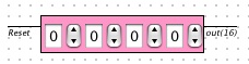
If the standard footprint is being used, the second line should be
setPolygon(null);
Plug-in controls are normally disabled when they are viewed in a splash display. This requires an override of setEnabled in the view class to enable/disable the controls. In our example we include the following:
    public void setEnabled(boolean enabled) {
	super.setEnabled(enabled);
	for (int i = 0; i < sLen; i++) spinners[i].setEnabled(enabled);
    }
A view rich with controls will require strong lines of communication with its document. The view will necessarily have to initialize its controls based on the document's state. It will generally have to call some method of the document as part of a control event. When respondint to an input event, the document may need to call methods of the view to change control values.
A well-designed plug-in will include useful methods in the document and view classes. The document uses getView(), while the view uses getDoc() (with proper casts) to invoke methods in the other class. Refer to the sample plug-ins in the tutorial and the SDK distribution for examples of document-view interaction.