Tutorial 1: The Basics
Tutorials
... Tutorial 1: The Basics
In this tutorial you will learn basic circuit-building techniques. We
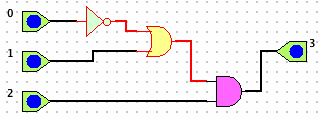
will build and test a simple 3-input circuit to compute O = ~A + (B
C). We will use 3 simple switches and one simple bulb. We will then save the project and export it to XML, then reload and
import it. Finally, we will use the circuit as a subcircuit.
Refer to Adding, Selecting, Copying, Moving, Deleting
and Connecting Components to learn how to place components on the
circuit board and to connect them.
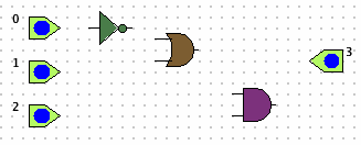
- Add 3 switches (
 ), 1 bulb (
  ), 1 OR-gate (
  ),
1 NOT-gate (
  ), and 1 AND-gate (
  ) to the circuit board,
as shown.
- Connect the components as shown.
- Right-click each of the switches, select Add/Delete Label and label them, A, B and C,
respectively. Do the same for the bulb and label it O.
Now click switch C to test the circuit.
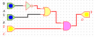
Try different switching patterns and observe the result.
- Select File | Save Project (
 ) and save the project as Proj1.cct.
 - Select File | Export XML Project and export the project as
Proj1.xml.
- Select File | New Project
- Select File | Load Project (
 ) and choose Proj1.cct.
 - Select File | New Project
- Select File | Import XML Project and choose Proj1.xml.
- Select File | New Project
- Select Elements | Add Card (
 ) and choose Proj1.cct.
 - Click on the circuit board. The card should appear.
- Add a switch bank (
 ) and click the spinner to
create 3 switches. Add a single bulb
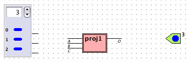
- Swipe across the pins of the switch bank and connect them to the
card's input pins. Connect the card's output pin and connect it to
the bulb. Click the switches to see the resulting output.
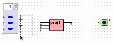
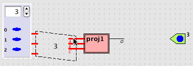

- Double-click the card to splash-view its structure.
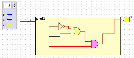
- Click Proj1 in the subcircuit window.
- Right-click Proj1 in the subcircuit window and select Export proj1 as chip.
- Select File | New Project
- Select Elements | Add Chip (
 ) and repeat steps 12 - 14 with the chip.
 ), 1 bulb (
  ), 1 OR-gate (
  ),
1 NOT-gate (
  ), and 1 AND-gate (
  ) to the circuit board,
as shown.


 ) and save the project as Proj1.cct.
  ) and choose Proj1.cct.
  ) and choose Proj1.cct.
  ) and click the spinner to
create 3 switches. Add a single bulb


 ) and repeat steps 12 - 14 with the chip.