Installation
DLSim 3 is distributed as the executable jar file DLSim3.jar. It
requires JRE v. 1.6 or later. To launch, type
java -jar DLSim3.jar(or double-click on the DLSim3.jar icon if supported by your machine).
Note: using DLSim 3 with larger circuits may require larger stack and heap allocations; e.g.
java -jar -Xss2028k -Xms500m -Xmx1695m DLSim3.jar
DLSim3.jar is contained in the zip file DLSim3.zip, which also contains numerous example circuits.
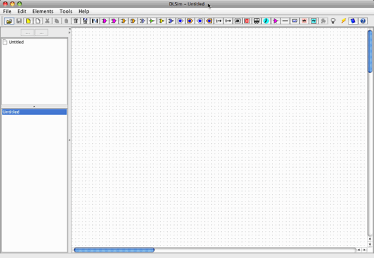
When properly installed, a running DLSim should look like this:
The GUI consists of several menus (File, Edit, Elements, Tools, Help), a toolbar and three windows: the Hierarchy Window, the Subcircuit Window and the Circuit Board.
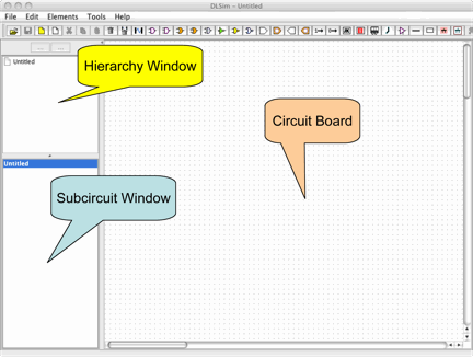
The Hierarchy and Subcircuit Windows present two views on the subcircuit structure of the current project. The Hierarchy Window shows the hierarchical structure of the subcircuits of the circuit currently in view while the Subcircuit Window provides a flat listing of all subcircuits in the project.
Logical circuits are constructed on the design canvas and saved to ".cct" files.
A circuit may contain several subcircuits abstracted as cards or chips.
A card can be "splashed" by double-clicking, or viewed by clicking it in either the Hierarchy or Subcircuit Window.
Complete circuit descriptions can be exported to XML and used to re-create an entire circuit hierarchy.
Circuit Construction
Circuits are constructed by connecting the various circuit
elements. The available circuit elements consist of the following
(running from left to right in the toolbar):
Adding an element. Left-click the element on the toolbar (or select the element from the Elements menu), then left-click on the design canvas where you want to place the new element. Right-clicking cancels the action.
- Gates:
- and, or, (2 and 3 input), xor, not, nand nor
- Constants:
- 1 and 0
- Endpoints:
- source (switch, switchbank); target (bulb, bulbbank)
- Other:
- JK flipflop, LED panel, clock, non-inverting buffer, connector, label, abstract circuits (cards & chips)
Selecting moving, cutting, pasting, deleting, etc. elements. Elements can be selected/deselected by left-clicking. Element groups can be selected by dragging a box around them, or shift-left-click to add/delete from the group, in the standard Macintosh fashion.
A group of selected elements can be moved by dragging on one of them. The group can be cut/copied/pasted using Edit | Cut (^X or TB  ), Edit | Copy (^C or TB
  ) and Edit | Paste (^V or TB
  ). The group can be deleted using Edit | Delete (
  ).
).
Connecting elements. The output of one element is connected to the input of another element as follows:
Bus Connections Parallel connections between pairs of elements are supported. See Circuit Design | Bus Connections for details.
Deleting connections. Connections can be deleted by selecting Edit | Delete Connection (or ). Click on the connected elements as when adding a connection. A connection is also deleted if one of its endpoints is subsequently connected to another element.
Action Menus. Each element has an popup menu containing appropriate actions. To activate, right-click the element.
Multiplicity. Many logical elements can function as multiple parallel instances. See Circuit Design | DLSim 3 Components for details.
Undo-redo. All actions can be undone/redone using Edit | Undo (^Z) and Edit | Redo (^Y).
A circuit is saved using File | Save (  ) or File | Save
As. All circuits are identified using the .cct extension.
) or File | Save
As. All circuits are identified using the .cct extension.
A saved circuit is loaded using File | Open Circuit (  ). A new empty circuit is created using File | New
Circuit.
). A new empty circuit is created using File | New
Circuit.
XML. A DLSim 3 circuit hierarchy can be exported to XML using File | Export XML Project. To import such a circuit use File | Import XML Project. You are encouraged to save frequently in XML format.
A saved circuit that is not already part of the subcircuit hierarchy
can be inserted onto the design canvas using Elements | Add Card (  ) or Elements | Add Chip (
  ). After selecting the
circuit file from the file dialog, left-click to place the abstract
circuit on the circuit board, as with any other element (right-click
to cancel). An abstract circuit appears as a card (pink) or chip
(green), with numbered input and output leads corresponding to the
switches and bulbs in the saved circuit. Connections to these leads
act as connections into the saved circuit.
). After selecting the
circuit file from the file dialog, left-click to place the abstract
circuit on the circuit board, as with any other element (right-click
to cancel). An abstract circuit appears as a card (pink) or chip
(green), with numbered input and output leads corresponding to the
switches and bulbs in the saved circuit. Connections to these leads
act as connections into the saved circuit.
Once a circuit has been loaded into the hierarchy, new instances can be added by dragging it from the Subcircuit Window onto the circuit board.
New main and subcircuits can be created through File | New Main
Circuit (  ) and File | New Sub Circuit (
  ), respectively.
A card can be "splashed" open/closed by double-clicking. Shift-double-click (or selecting the card in the Hierarchy or Subcircuit Window) opens the card on the circuit board for possible editing. Saved edits will be introduced into the card instances.
Note: Edits affecting the endpoints of a subcircuit will disconnect all associated card instances.
A chip cannot be viewed or edited.
An abstract circuit can be saved while it is being viewed by using the circuit's Action Menu (right-click on the circuit in the Subcircuit Window.) You may save the circuit either as a card or chip.
Using DLSim 3 as an Applet
DLSim 3 can be run as an applet in a Web browser as a convenient way
of deploying demo circuits. See Overview | Using
DLSim 3 Applets for details.
Connectors. Connectors are used for layout purposes and to split an input into multiple outputs. See Circuit Design | Connectors for more detail.
Labels. Labels can be added to the design canvas like any other element. Double right-clicking on the label permits choice of font and style.
Labeled terminals. Switches and bulbs can be labeled using a selection from their Action Menu. Label text appears on chip leads of an abstracted circuit.
Lights. Clicking lights "off" using Tools | Lights
On/Off (  ) makes it easy to follow circuit paths.
Clock. Use the Action Menu to set clock speed.
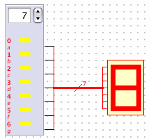
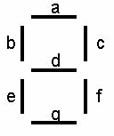
LED. Each LED lead lights one horizontal or vertical segment in the LED. A completely lit LED and the LED segment map are shown below.
Plug-ins. Plug-ins are user-defined components that extend the component palette for special purposes. They are implemented as extensions to the Java Plugin class. Plug-ins are distributed in jar files Plugins.jar, Plugins0.jar, Plugins1.jar, ..., Plugins9.jar. Plug-ins will be loaded if one or more of these files is present in the same directory as DLSim3.jar.
Plug-ins are loaded from menus obtained by clicking
TB  . They are managed like any other component.
Plug-ins may contains Java Swing controls. Consult the documentation supplied by the plug-in author for specific instructions.