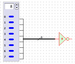
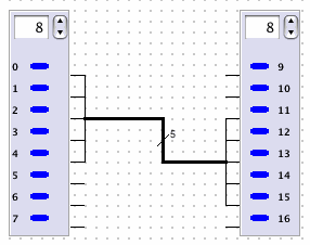
DLSim 3 supports parallel connections (i.e. buses) between pairs of components. Bus connections can be made between three different types of pin configurations of the same width n:
Note that the endpoints need not be the of the same type as long as the widths match. For example, 8 output pins on a component can be bus connected to a bank pin of width 8 on a subcircuit. Example:

All connections involve selecting initial and final endpoints. The initial endpoint can be either input or output. Connecting to a single-pin bus endpoint (either initial or final) is the same as connecting to an ordinary pin; simply click the pin.
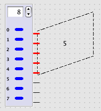
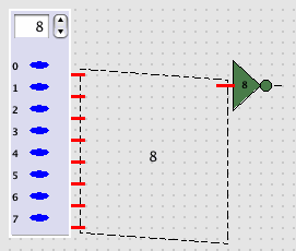
To initiate a bus connection from a multi-pin endpoint, do the following:
 .
. 
Selecting the final endpoint:
If the endpoint is multi-pin, click the top pin of the endpoint; e.g.
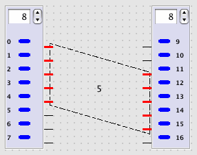
if the endpoint is single-pin simply click the endpoint. For example:
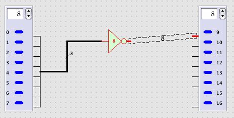
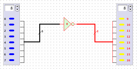
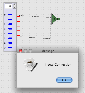
Note: Attempting to connect endpoints of different widths will result in an error.
