), 2 bulbs (
  ), 2 three-terminal
connector (
), 2 three-terminal
connector (  ), (see Connectors), an AND-gate
(
), (see Connectors), an AND-gate
(  ) and an XOR-gate (
  ) to the circuit board; label the
endpoints and connect the components as shown:
) to the circuit board; label the
endpoints and connect the components as shown: 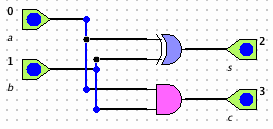
 ) and save as
halfadd.cct.
) and save as
halfadd.cct. In this tutorial we will build an 8-bit adder in four stages: half-adder, full-adder, 4-bit adder and 8-bit adder.
I. Building a half-adder
), 2 bulbs ( ), 2 three-terminal
connector ( ), (see Connectors), an AND-gate
( ) and an XOR-gate ( ) to the circuit board; label the
endpoints and connect the components as shown:
) and save as
halfadd.cct. II. Building the full-adder
 ). Drag 2 halfadd cards from the subcircuit window.
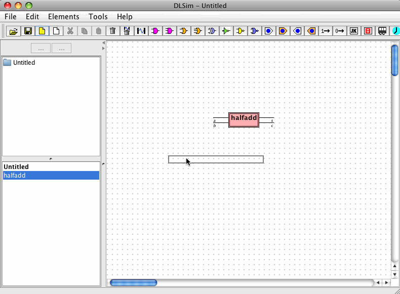
 ), 1 bulb bank (
  ),
and an OR-gate (
),
and an OR-gate (  ); label the endpoints and connect as shown.
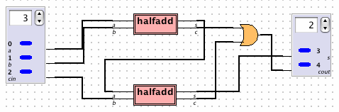
III. Building the 4-bit adder
 ) and choose fulladd.cct. Click
on the circuit board to add the fulladd card. ), 1 single switch, 1 bulb
bank ( ), and 1 single bulb (in that order); label the
endpoints and connect as shown. Select Use Bank Pin from the
Action menus of the three terminal banks. (See Subcircuits:Special Topics: Bank Pins and LEDs).
) and choose fulladd.cct. Click
on the circuit board to add the fulladd card. ), 1 single switch, 1 bulb
bank ( ), and 1 single bulb (in that order); label the
endpoints and connect as shown. Select Use Bank Pin from the
Action menus of the three terminal banks. (See Subcircuits:Special Topics: Bank Pins and LEDs). 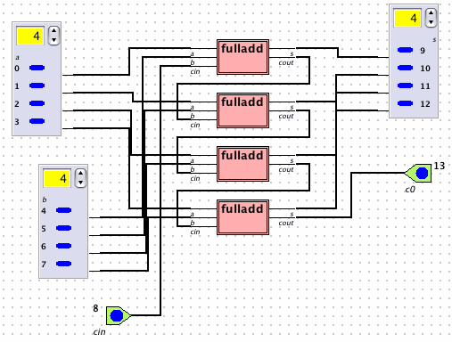
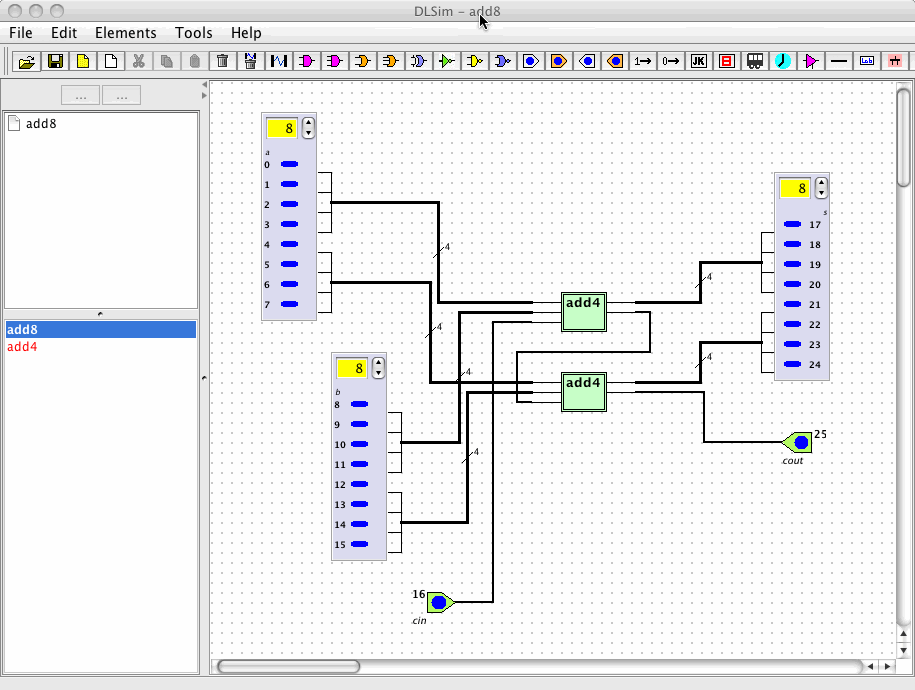
IV. Building the 8-bit adder
 ) and choose add4.chp. Click
on the circuit board to add the add4 chip. ), 1 single switch, 1 bulb
bank ( ), and 1 single bulb (in that order); select bank
pins, label the endpoints and connect as shown.
) and choose add4.chp. Click
on the circuit board to add the add4 chip. ), 1 single switch, 1 bulb
bank ( ), and 1 single bulb (in that order); select bank
pins, label the endpoints and connect as shown. 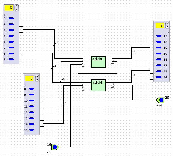
V. Importing add8