Containers are components that hold one or more instances of a Capsule for use within a host (or parent) Capsule. The elements of a Container are called members or elements. Containers interface with the components in their parent through Connector Pins, which are represented as horizontal lines on the left and right side of the container body. (Left and right sides correspond to input and output pins, respectively.) Every Connector Pin is given a label, and they correspond roughly to the DataInputs and DataOutputs (i.e., the Interface) of the constituent Capsule type(s), although some Containers add pins. Pin connection uses a common dialog format for all Containers and is shown below.
Pins are addressed using dot notation. If Container X has Pin Y, then X.Y is a reference for the Pin.
Each container type extends and enriches the environment of its elements by assigning new functionalities that are only valid within the context of the container. These new functionalities are realized by a set of primitive operators (primops) provided by the Container. (We refer to such primops as service providers.) The data structure of the container together with the service providers comprise an abstract data type that effects a specific topological environment.
Every aggregator has a means for uniquely identifying its members. We'll refer to this as its Aggregator Id.
Examples:
- A Chip binds the property
Superto reference the State Object of the Chip's parent (a State Object is a NovaScript object that binds each component in a Capsule to its value in the current timestep). This is used by the Chip's DataInputs to channel component data from that parent into the Chip. - An AgentVector assigns a unique Agent Id to each element (or agent) and provides the means for interaction between agents using these ids for indentification. It also represents location and trajectory parameters in the virtual space provided by the AgentVector in which its agents dwell. An AgentVector also supports agent lifetime management (i.e., births and deaths).
- A CellMatrix assigns matrix Coordinates to each of its elements and supports interaction between its members (or cells) using these coordinates for identification.
- A SimWorld combines an AgentVector with a CellMatrix, so that the virtual agent space of AgentVector corresponds to the topological space created by the CellMatrix.
Connecting Container Connector Pins to components in the host Capsule
- Right-click the Container to open its Properties Window. This window will contain a Connector Dialog, as shown below.

- The Input and Output Selector choosers let you select the pin you wish to connect. Eligible selections are displayed in the Input and Output Target lists. You can select only a single input for each Input Target, however multiple outputs may be selected by using the Shift Key when selecting.
- By rotating through all of the Input and Output Selector entries, connections can be specified for all connector pins. For those that are to remain unconnected select "None".
- When a connection set has been accepted (by closing the Properties Window) dashed lines called connector lines will indicate the connections made to each pin. Connector line visibility is controled by the current Tools | Arrow {On, Highlight, Off} mode.
Standard Aggregate I/O Protocol
Most aggregator Connector Pins represent components of the Capsule Interface (i.e., the DataInput/Output components) of their elements. As such, each creates either a one-to-many (input) or many-to-one (output) data connection between the Aggregator and the component at the other end of the connection in the parent Capsule (i.e., the connection's source for input or target for output). To provide maximum flexibility the following protocol is used:
Input- If the source expression produces an ordinary NovaScript data structure (i.e., number, string, array, or object), that value is broadcast to all elements of the aggregator.
- If the source expression is a function, that function is applied to the Aggregator Id of each element, and the resulting value is used only with that element.
Output
- If the target is a plugin pin expecting input from the aggregator, the data is handled accordingly; otherwise
- The output pin is treated like a function that inputs the Aggregator Id and returns the value for the pin's DataOutput in the corresponding element.
Example

The right-hand figure shows AgentVector Universe containing a Capsule type whose Interface, comprised of 2 DataInputs and 1 DataOutput, is shown at left. Since this is an AgentVector, Init_Count and AData pins are added to the Interface pins on Universe (see AgentVector, below). The Term Initial_Count contains a scalar value initializing the size of Universe (note: the "10" appearing in the component is a default value only, used only if the Init_Count pin is not connected.) Similarly, the AData pin is connected to a corresponding AData pin on the AgentViewerX stub for UniverseView.
If we assume that the Term Speed_Input represents a common speed for all agents, then Speed_Input can contain a scalar numerical value that is broadcast to all Speed DataInputs among the Universe elements. However, if we want to initialize State_In differently in each element, we can use an expression of the form function(id){...}in the Term State_In_Input that will be applied to each Agent Id to determine the value for that agent's State_In DataInput.
The State_Out pin is connected both to an input on UniverseView and to the Term State_Out_Output. The UniverseView pin, which has the label AgentColorIn, expects to be connected to an AgentVector Interface output pin and can process its data accordingly; the Term State_Out_Output can access the State_Out values of specific agents by treating the pin as a function: i.e., using expressions such as Universe.State_Out(id).
 A Chip encapsulates an instance of a Capsule to act as a submodel within a host Capsule. More than one Chip containing instances of the same Capsule, or different Capsules, may appear in a single parent. Large Nova models can be built using stacks of submodels based on a well-structured design pattern.
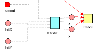
 An AgentVector is a one-dimensional array of Capsules (i.e. a vector) which has been extended to support location, trajectory and lifecycle functionalities. We refer to AgentVector members as